An illustrative mechanism study by MareForge. All numerical requirements are hypothetical; the concept has not been manufactured or tested.
Adding a second support roller can appear to halve the load on each roller. That assumption depends on how the two contacts deform and whether the mechanism can accommodate differences in height.
This study explores a removable roller cassette with a central rocker pivot. Its purpose is to redistribute a slowly applied normal load between two contacts. The design question is whether passive movement can tolerate variation without consuming all the available travel or making the equipment difficult to service.
A small height error can produce a large imbalance
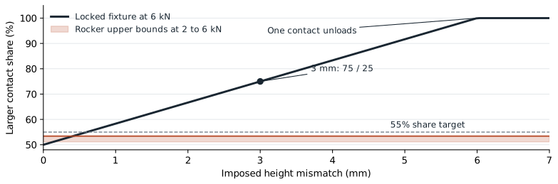
A guided platen and two compression springs provide a simple benchmark. The springs represent two compliant interfaces, not a validated model of cable contact. With the support geometry locked, equal stiffness and both contacts engaged, the force difference is the stiffness multiplied by the height mismatch.
At a total normal load of 6 kN, an interface stiffness of 1 kN/mm and a 3 mm mismatch, the contacts carry 4.5 and 1.5 kN. That is a 75/25 split, even though two rollers are present.
At a 6 mm mismatch in the same benchmark, one contact unloads completely. The lower reaction must then be set to zero; a spring calculation that retains a negative contact force would misrepresent the physical system.
Give the supports a degree of freedom
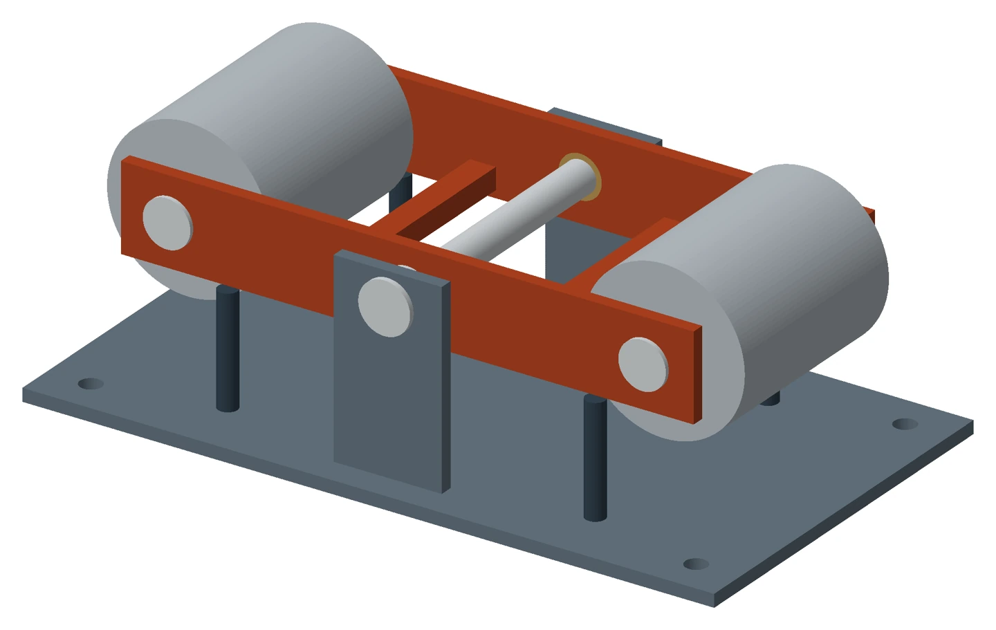
The proposed cassette carries both rollers on a common rocker, with equal arms about a central pivot. The rocker can change the relative height of its ends.
For vertical contact forces, the load difference is constrained by the net moment about that pivot. If the pivot were ideal and there were no other pitch moments, the reactions would be equal. A real mechanism has resistance and bias from bearings, seals, mass eccentricity and the handled interface.
The sample therefore sets an explicit requirement: neither contact should carry more than 55% of the total benchmark load between 2 and 6 kN. For the selected 220 mm half arm, the lowest load governs the allowed net moment. It gives a ceiling of approximately 44 N m; the study selects a lower 30 N m test budget.
Under that budget, the larger contact share is bounded at 53.4% at 2 kN. At the 6 kN, 3 mm baseline, the calculated signed moment case gives 3.068 and 2.932 kN, approximately 51/49.
The compact version spends its travel too early
The rocker needs movement for external height mismatch, assembly variation and unequal elastic compression. Those demands add together in an unfavourable combination.
The study allows 8 mm of external mismatch, a 1 mm differential assembly allowance, interface stiffnesses between 0.8 and 1.2 kN/mm, and a working pitch range of ±1.5 degrees. It also requires at least 1 mm of remaining differential travel reserve.
| Roller pitch | Available differential travel | Required travel bound | Remaining reserve |
|---|---|---|---|
| 360 mm | 9.424 mm | 10.424 mm | -1.000 mm |
| 400 mm | 10.471 mm | 10.406 mm | 0.064 mm |
| 440 mm | 11.518 mm | 10.392 mm | 1.126 mm |
The 400 mm option accommodates the mathematical demand but leaves almost no reserve. The 440 mm pitch is the shortest of the three options that meets the full study requirement. Its larger footprint is the cost of accommodating the declared variation.
The benefit disappears when the pivot cannot move
A stop contact or seized pivot changes the load path. The free rocker relationship no longer establishes the same sharing performance. Each roller, its axle and the supporting structure therefore need assessment for adverse load distributions, including the full applied normal load on one roller where relevant.
The CAD concept separates the ±1.5 degree analysed working range from stop envelopes near ±2 degrees. The companion note records the sampled geometry checks and the remaining structural work. These are geometric results, not proof of stop strength or operating safety.
Removal space is part of the design
The cassette uses a transverse removable pivot pin and replaceable bushes. Its 306 mm pin leads to a proposed side access allowance of about 350 mm for withdrawal and handling. If a vessel interface cannot provide that space, removing the whole base or changing the support architecture may be preferable.
The next useful step is a fixture test that measures both reactions, pitch, breakaway moment and hysteresis while reversing the imposed mismatch. Cable curvature, local compression, lateral containment, fatigue and environmental suitability require their own evidence.
Load equalisation through tilting supports is established practice; Kingsbury describes the principle in thrust bearing arrangements. This cassette is an original illustrative application, with no claim that the reference validates its performance.
For Marine and Offshore Engineering, the relevant inputs are the route, loads and installation constraints. A defined mechanism can progress through Equipment and Product Development. Where those inputs are incomplete, Technical Assessment and Concept Definition provides a starting scope.
Discuss a related requirement
Share a short, non-confidential outline of the equipment, the decision you need to make and the known constraints.
Contact MareForge about this topic