A temporary cable guide connects an operational requirement to a mechanical load path. The cable route determines the load on the sheave and axle; the cable's bending limits constrain the geometry. Both need to be understood before a concept becomes a detailed equipment design.
This illustrative example considers a freely rotating sheave on a stationary axle for a deck handling operation. All numerical inputs are hypothetical. It is a worked explanation of engineering decisions, not a client case study, tested product or approved equipment design.
From cable tension to axle load
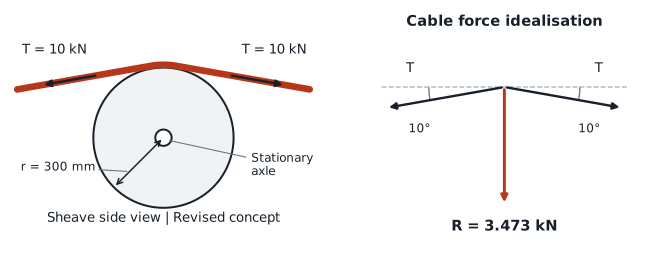
Assume a cable tension of 10 kN in each leg and a direction change of 20 degrees. The route is symmetric in a vertical plane. With equal tension and negligible friction, the horizontal force components cancel and the downward cable reaction is:
R = 2 T sin(θ/2) = 3.473 kN
Here θ is the change from a straight cable route. The two outward tension vectors are 160 degrees apart.
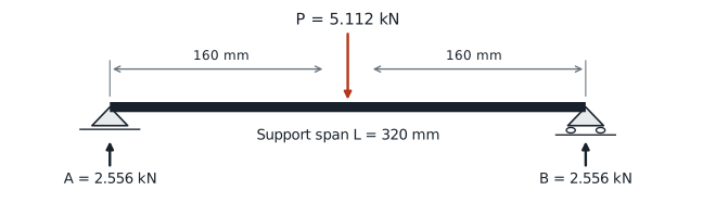
For this calculation, an assumed multiplier of 1.40 is applied to the cable reaction, followed by a 0.250 kN dead load allowance:
P = 1.40 R + 0.250 = 5.112 kN
This is a screening assumption, not a code derived safety factor. It does not establish the response to snagging, a seized sheave, out of plane loading or vessel motion. The dead load allowance also needs to be replaced by the final sheave and axle mass.
Why stiffness can change the axle choice
Model the axle as a uniform solid circular beam, simply supported over 320 mm with the total load applied at midspan. Use an assumed elastic modulus of 200000 MPa, a nominal bending stress target of 100 MPa and a bending deflection target of 0.20 mm. These are explicit comparison criteria for the example, not qualified material allowables.
| Axle diameter | Nominal bending stress | Bending deflection | Comparison with the assumed targets |
|---|---|---|---|
| 30 mm | 154.3 MPa | 0.439 mm | Both exceeded |
| 35 mm | 97.2 MPa | 0.237 mm | Deflection exceeded |
| 40 mm | 65.1 MPa | 0.139 mm | Both met in this model |
The 35 mm option is below the stress target but exceeds the deflection target. Increasing to 40 mm reduces bending stress by 33% and bending deflection by 41% relative to 35 mm. The 40 mm section can therefore be carried into the next design iteration under these assumptions.
This is a nominal beam calculation. Bearing contact, local axle features, shear deflection, fatigue and support flexibility still require evaluation. The accompanying technical note gives the equations, units and reproducible results. The beam model follows the classical formulation presented in MIT OpenCourseWare Chapter 10 Deflections due to Bending, printed page 269.
Check the cable path independently
Assume a 24 mm cable with a minimum inside bend radius of 250 mm. This limit is hypothetical and must be replaced by manufacturer data for the actual cable and operating tension.
A 400 mm groove root diameter gives an inside bend radius of 200 mm, below the assumed minimum. A 600 mm alternative gives 300 mm and satisfies this geometric comparison. Its additional mass, inertia and space requirements must feed back into the equipment design.
The corresponding cable centreline radius is 312 mm. For an ideal flexible cable at 10 kN, the normal contact line load is approximately 32.1 kN/m. That is not a contact pressure in MPa: groove contact width, cable stiffness and allowable local compression have not been established.
A route change can alter the result
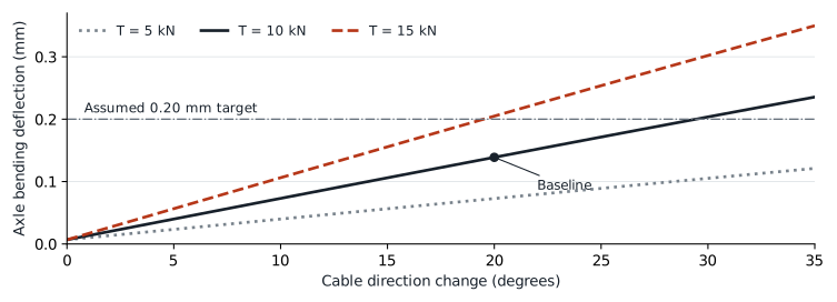
At 10 kN, increasing the direction change from 20 to 30 degrees raises the axle load to 7.497 kN. Nominal bending stress remains below the assumed target at 95.5 MPa, while bending deflection rises to 0.204 mm and exceeds the 0.20 mm target. The baseline result therefore cannot be extended to other routes without recalculation.
What completes the engineering package
Further design requires confirmed cable limits and operating loads, checks of the complete support and deck attachment, qualified material and bearing selections, and detailed drawings with fits, tolerances and inspection requirements. The risk review must address cable retention, pinch points and access. Functional or load testing must be defined for the intended equipment and use.
Vessel routing and deck interfaces belong within Marine and Offshore Engineering. A defined concept can progress through Equipment and Product Development. Where cable data, loads or interfaces are incomplete, Technical Assessment and Concept Definition provides a starting scope.
A useful initial enquiry includes the cable data sheet, route sketch, tension envelope and available installation space.
MareForge technical note MF-TN-001, revision 1.0, 12 September 2026. Original illustrative calculations and figures. No equipment rating, prototype testing or independent design approval is claimed.
Discuss a related requirement
Share a short, non-confidential outline of the equipment, the decision you need to make and the known constraints.
Contact MareForge about this topic