Illustrative engineering study · MF-TN-003 · Revision 1.0
A piece of equipment can fit its operating position and still be difficult to remove for maintenance. The missing space may be at a corner, behind a connector or beneath the equipment where a handling device needs to enter.
This original MareForge study examines a hypothetical auxiliary equipment module in a confined vessel bay. We compare two removal architectures, define a continuous geometric route and identify the interfaces that make the selected concept usable. All dimensions and equipment envelopes are illustrative. This is a concept study, not a completed vessel project or a tested product.
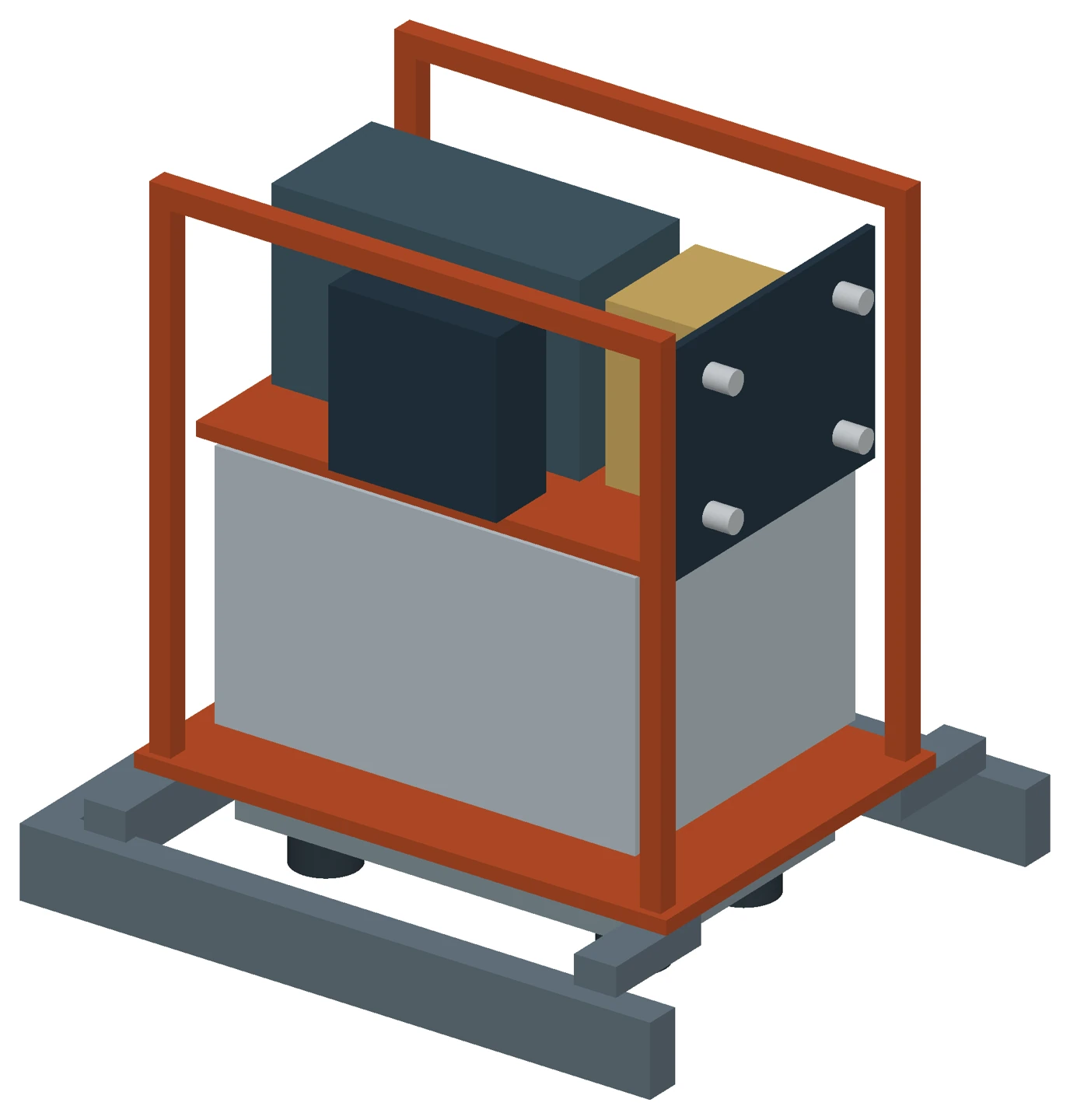
Start with the removable boundary
The original complete skid occupies a 900 × 800 mm footprint. It fits inside the 1000 mm wide operating bay, but the exit corridor is only 700 mm wide. Keeping the skid upright, no plan orientation can reduce its minimum overall projected width below 800 mm. Removing the complete skid is therefore incompatible with that corridor.
The design decision is what needs to leave the vessel during maintenance. We compare:
- Split modules: a 640 × 480 mm reservoir module and a 640 × 400 mm power module. Both footprints have ample room on the declared route, but separating the groups creates fluid interfaces that must be disconnected and reinstated.
- A removable cassette: the grouped equipment leaves as a 760 × 540 mm cassette while the docking frame stays in place. This retains the interconnections between the equipment groups within the removable boundary.
We select the cassette for this hypothetical brief because it meets the geometric allowance without splitting those groups. The choice remains conditional on its actual mass, handling requirements and maintenance tasks. A split arrangement could become preferable if those inputs change.
This is a typical interface between Marine and Offshore Engineering and Equipment and Product Development: the available vessel space changes the equipment architecture.
The turning pocket controls the footprint
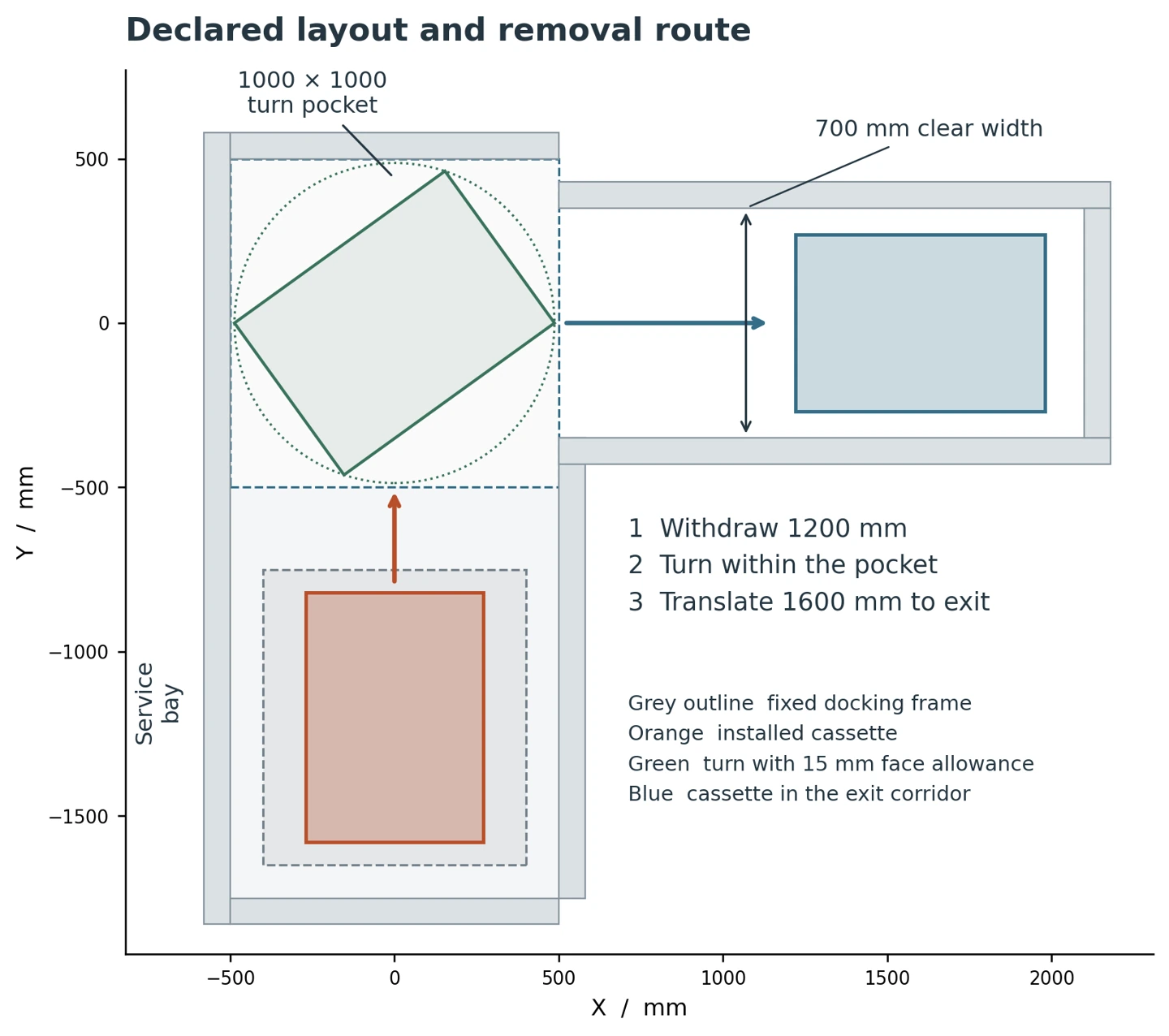
The cassette must leave the bay, turn through 90 degrees within a 1000 × 1000 mm pocket and move into the exit corridor. A doorway-width check alone does not establish that route.
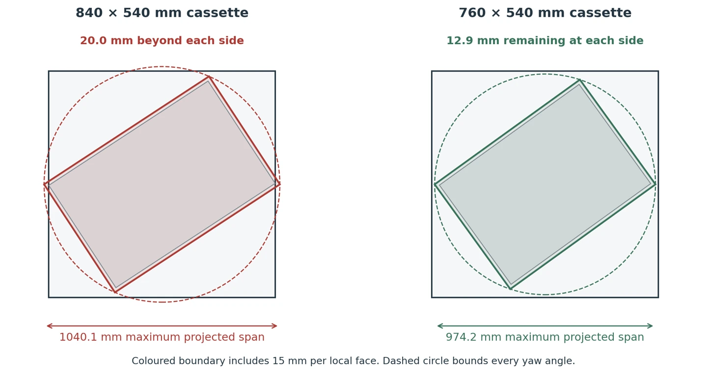
An initial 840 × 540 mm cassette has a diagonal of 998.6 mm. It just fits an ideal centred rotation within the square, with only 0.7 mm remaining at each side at the most demanding angle.
That result leaves no useful room for dimensional and positioning allowances. For this study, we allocate 15 mm to each local face of the moving outline: 5 mm for survey and fixed-obstacle uncertainty, 3 mm for the build envelope and 7 mm for positioning. These are declared assumptions, not standard tolerances or measured accuracies.
The expanded 840 mm trial becomes 870 × 570 mm, with a 1040.1 mm diagonal. It no longer fits the reserved turn.
The selected 760 × 540 mm cassette expands to 790 × 570 mm. Its diagonal is 974.2 mm, leaving 12.9 mm per side beyond the expanded envelope. In the aligned 700 mm corridor, the corresponding remaining side clearance is 65 mm.
Verify motion between the screenshots
For this route, the geometry can be checked continuously. The two translations have simple swept rectangular bounds. During the centred turn, a disk with radius equal to half the expanded diagonal contains the moving rectangle at every angle.
Those bounds fit inside the declared free space and connect at common end positions. They establish a continuous clear route under the study assumptions. Reversing the motion provides the same geometric installation path.
A separate collision calculation checked 921 positions, with zero wall intersections. CAD Boolean checks at eight representative positions also found no interference. These checks support the model consistency; the analytical bounds establish clearance between positions.
Allow space to disconnect and support the equipment
The initial rear-facing connection arrangement fails a separate access check. A 220 mm tool and connector withdrawal reservation extends 50 mm into the aft wall. Moving the service panel to the front makes the same reservation clear before the cassette moves.
The lifting carrier also needs allocated space. In this concept, its 600 × 360 mm outline passes between docking pads with 400 mm between their inner faces. A 50 mm lift stroke takes up a 10 mm initial gap and then raises the cassette by 40 mm. The tray clears the locator tops by 30 mm before withdrawal.
These dimensions reserve an interface for a handling solution. They do not qualify a carrier, establish a load rating or demonstrate stability. External hoses and cables must be detached and secured clear before the defined transport envelope applies.
The docking frame has its own replacement question. We divide it geometrically into two 900 × 200 mm side frames and a 700 × 50 mm cross member. Their footprints meet the same turn and corridor allowance. Accessible joints and deck fixings remain part of the detailed design.
What this study establishes
The useful result is a defined removable boundary, a verified geometric route and a front service interface supported by a measured space reservation. These are concrete inputs to the next design stage.
The study does not establish equipment performance, structural strength, handling stability, human access or compliance. Actual supplier dimensions, mass and centre of gravity, deck conditions, door hardware, overhead services and connection requirements would need to replace the assumptions before applying the concept to a vessel.
Where those inputs are incomplete, a Technical Assessment and Concept Definition can establish the available route, compare removable boundaries and define the next engineering scope.
The companion technical note sets out the equations, geometric checks and scope limits for this illustrative example.
Watch the removal route
The cassette withdraws, turns in the reserved pocket and enters the corridor. This illustrates the declared geometry after disconnection and lifting.
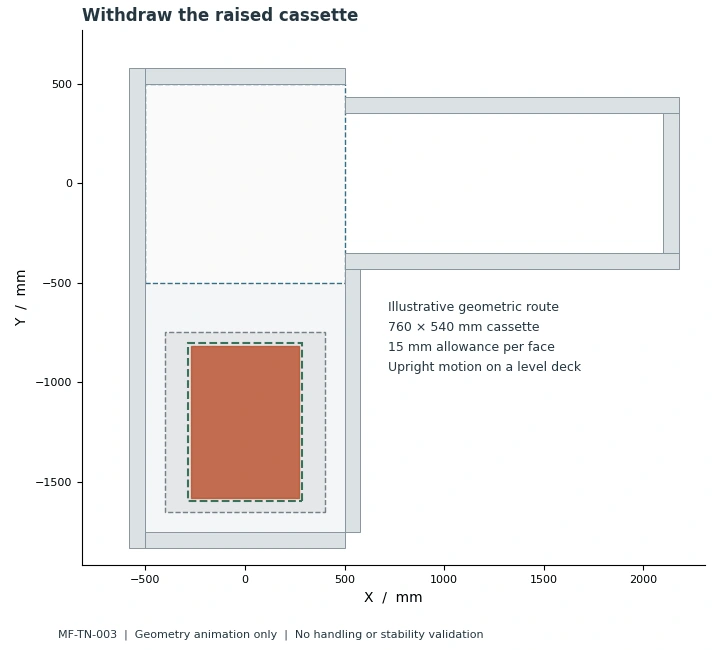
Illustrative geometric sequence. Handling capacity and stability are outside this study.
Discuss a related requirement
Share a short, non-confidential outline of the equipment, the decision you need to make and the known constraints.
Contact MareForge about this topic